
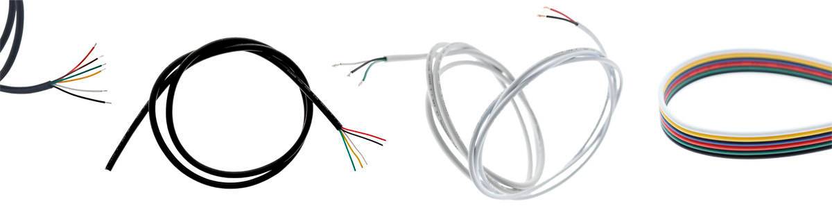
Wiring for LED lights is one of the most important, yet often overlooked, parts of a lighting system. Properly selected and correctly installed cables ensure reliable operation, smooth control performance, and overall lighting safety.
In this article, we go through the types of cables required for LED lighting in different systems—such as DALI, Zigbee, Triac, and other control methods—and explain how lights features and power supply types affect wiring. At the end, you’ll also find practical tips for a safe and efficient installation.
Smart Home Automation and Control Systems
Cabling for DALI
DALI (Digital Addressable Lighting Interface) is a professional, bidirectional lighting control system. It uses its own control bus, which can be run in the same cable as the supply voltage, provided the wiring complies with the DALI standard.
- In typical DALI installations, a 5 × 1.5 mm² cable or an equivalent cable is used.
- The control line can be up to 300 meters in length, provided the total loop resistance remains below 2 ohms.
- A DALI line can connect multiple lights and control devices on the same bus.
A centralised DALI group power supply simplifies installations in larger projects. Keep in mind that a single DALI master typically supports up to 64 devices. By using group power supplies, you can reduce the number of addresses required.
See our DALI products
Zigbee and other wireless systems
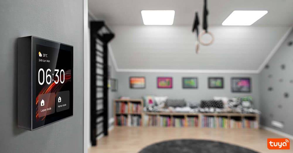
Zigbee, Wi-Fi, and Bluetooth Mesh enable wireless control, but cabling is still required for power supply. Control signals are transmitted wirelessly, while the LED luminaires are still powered via a low-voltage DC cable from the power supply. This means no control wiring is required for wall switches!
- Avoid long cable runs (over 15 m) to keep voltage drop from the power supply to a minimum.
- Use shielded cable if the wiring runs alongside other electrical cables.
- We recommend using group power supplies (typically 24 V) to keep system control clear and well organized.
Explore LedStore's Zigbee products.
Learn more about Tyua Smart Home
Triac dimming (230V)
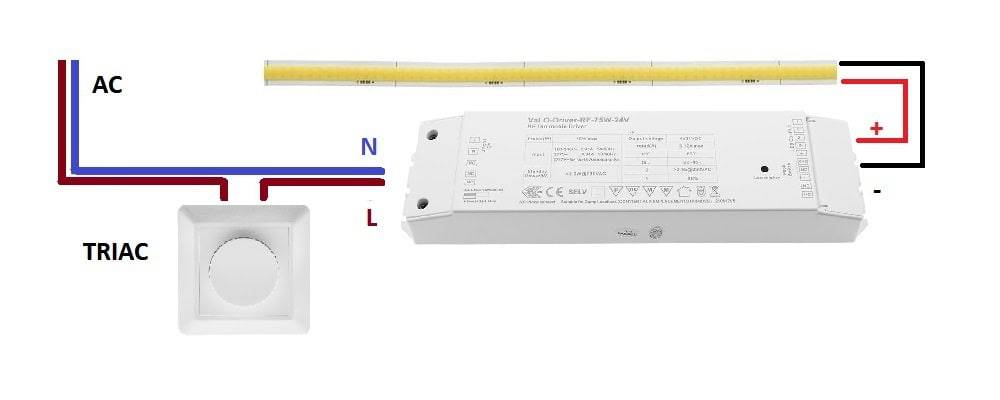
Triac dimming is a traditional and straightforward way to control LED lights directly from the 230 V mains supply. The wiring is typically similar to that used for conventional halogen lighting.
- A 3-core cable (L, N, Earth) is typically used, even though most high-quality power supplies are Class II (double-insulated) and do not require an earth connection.
- A dimmable LED requires a TRIAC-compatible power supply.
- Typically, a cable of 3 × 1.5 mm² is used.
LED light features and cabling
The technical characteristics of a light determine how many conductors are required in the cable. This is especially important when different color temperatures or colors of the lights are controlled. Wiring should be planned before the cables are installed, to avoid the need for corrections later on.
Here, we are referring to the cable that runs between the power supply and the lights.
Wiring for single-color LED lights
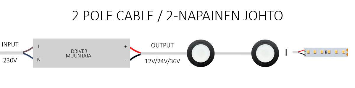
Single-color LED lights use a 2-core cable: positive (+) and negative (–). They are installed in the same way as shown in the TRIAC wiring diagram above.
- Connections : + red (usually), - black (usually)
- Use a 2 × 0.5 mm² cable for short runs (max. 15 m); for longer runs, use 2 × 0.75 mm² or thicker.
Wiring for CCT LED lights (tunable white)
CCT (Correlated Color Temperature) lights contain both warm white and cool white LED elements, which are controlled separately. This requires a 2- or 3-core cable.
A 2-core CCT light operates by rapidly switching the polarity between positive and negative 1,000 times per second, which is not visible to the human eye. This is how both color temperature and brightness are adjusted.
- Connections: - CW (cool white), + WW (warm white).
- Use a 2 × 0.5 mm² cable for short runs (max. 15 m); for longer runs, use 2 × 0.75 mm² or thicker.
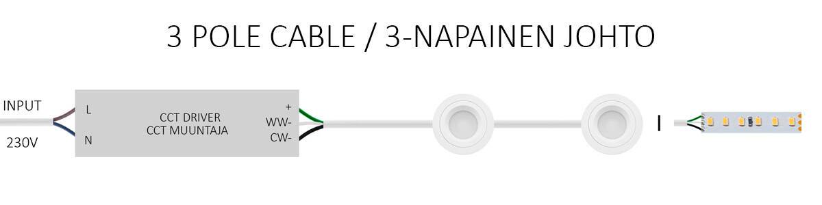
A 3-core CCT light (the most common type) operates with a shared positive (+), while the voltages to the cool and warm white channels are adjusted so, that the total voltage remains constant. At the midpoint, the voltage must not double (full power to both cool and warm at the same time), as this would damage the lights.
- Connections: + (shared), CW (cool white), WW (warm white).
- Use a 3 × 0.5 mm² cable for short runs (max. 15 m); for longer runs, use 3 × 0.75 mm².
RGB and RGBW lights
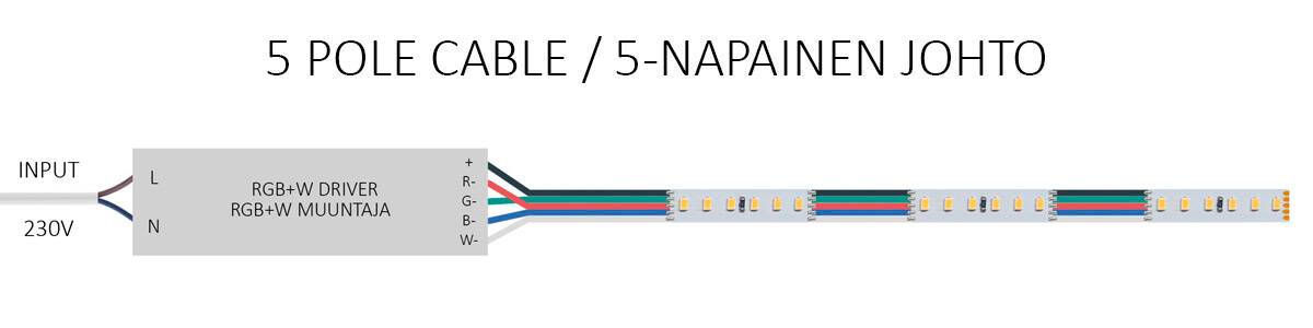
In RGB lights, each color (red, green, and blue) requires its own conductor, along with a shared positive conductor. Wiring is done using a 4-core cable. RGBW adds a fourth channel for the white LED, which requires a 5-core cable.
- Connections: + (shared), RGB = 4 conductors, (R, G, B, +)
- Connections: + (shared) RGBW = 5 conductors (R, G, B, W, +)
- Use a 4/5 × 0.32 mm² cable for short runs (max. 10 m); for longer runs, use 4/5 × 0.5 mm²
RGB+CCT systems
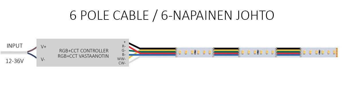
RGB+CCT combines color lighting and tunable white in a single luminaire. This means the wiring is done using a 6-core cable. In addition, RGB+CCT LED strips are controlled via a receiver installed between the power supply and the LED strip. This means you need a standard power supply as well as a receiver compatible with your control system.
- Connection for RGB, warm white, and cool white requires 6 conductors (R, G, B, warm white, cool white, +)
- Always use a high-quality, soft-sheathed, double-insulated LED cable.
- Check that the controller and the light support the same wiring configuration.
Explore LedStore's cable selection.
Discover LedStore’s Interconnect Cable Solutions
Wiring with Individual Power Supplies vs. Group Power Supplies
LED Lights with Individual Power Supplies
Each light can be fitted with its own power supply. This is a simple and fast solution, especially for renovation projects where centralised control is not desired or where it is not possible or practical to install an access hatch for a group power supply.
- Each light has its own 230 V power supply connection.
- The power supply can be concealed within the ceiling structure or placed behind the ligh through the same opening.
- Less planning is required, but there are more connections.
- With TRIAC power supplies, color temperature is selected using a switch during installation (dimming is supported, but continuous CCT adjustment is not available after installation).
- With DALI or Zigbee, each light has its own address (a more labor-intensive solution, but it allows continuous CCT adjustment even after installation).
Group Power Supplies and Centralised Solutions
A system with a group power supply means that a single high-capacity power supply feeds multiple LED lights. This reduces the number of heat sources, simplifies maintenance, and ensures that all lights in the group follow dimming and color temperature adjustments together.
- In 24 V systems, cable thickness is critical: cables that are too thin will cause voltage drop. e.g. 0,5 mm² max, 10-15 metres
- Keep the total cable length from the power supply to the lights under 15 m, or increase the conductor cross-section.
- Install the power supply in an easily accessible location, such as behind an access hatch, above cabinets, or in an electrical cabinet.
Practical tips and installation recommendations
- Choose the correct conductor cross-section: Under 10 m: 0.5 mm² / 5–15 m: 0.75–1.5 mm² / Over 15 m: 2.5 mm² or larger.
- Consider the voltage: voltage drop is greater in 12 V systems than in 24 V systems.
- Place controllers and power supplies thoughtfully: easy to access for maintenance, but discreetly concealed.
- Use high-quality connectors and tapes: they withstand heat and last over time.
- Document the installation: label power supplies, cable runs, and controllers for future maintenance.
Summary
| Type of light | Amount of Cables | Typical voltage | Control Method |
|---|---|---|---|
| Single-colour | 2 | 12/24V | ON/OFF or dimming |
| CCT | 2/3 | 12/24V | Tunable White |
| RGB | 4 | 12/24V | Colour Control |
| RGBW | 5 | 12/24V | Colour Control + White |
| RGB+CCT | 6 | 12/24V | Full Colour Control and Tunable White |
Summary
Proper LED light wiring ensures that the lighting performs exactly as designed—dimming smoothly, changing colors accurately, and operating reliably for years without issues. Well-planned lighting and electrical design from the outset helps avoid problems during installation.
